ENKI Engineering integrates vehicle–track interaction, supporting structures, ground propagation and receiver response into a complete engineering framework. Our work spans prediction, assessment, mitigation and design for railway-induced vibration and ground-borne noise.
Analytical and semi-analytical methods, finite-element modelling, corridor-wide vibration mapping, system diagnostics and trackform mitigation are selected according to the physical complexity and requirements of each project.
The complete railway vibration system
Vibration prediction requires a connected description of excitation at the wheel–rail interface, track dynamics, infrastructure response, wave propagation and building response. ENKI's modelling framework considers these interacting subsystems rather than assessing isolated components independently.
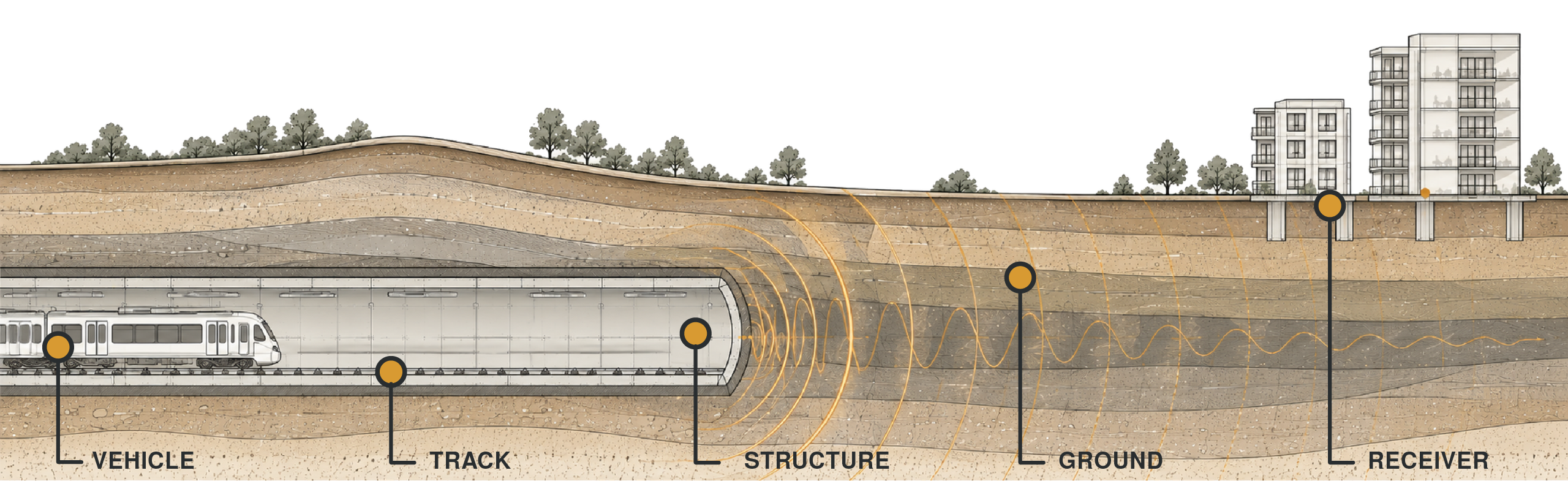
SOURCE
Vehicle dynamics and wheel–rail excitation
TRACK
Fasteners, slabs, ballast and track receptance
STRUCTURE
Tunnel, viaduct and foundation dynamics
GROUND
Wave propagation and soil–structure interaction
RECEIVER
Building vibration and re-radiated noise
Analytical, semi-analytical & finite-element modelling
Different modelling techniques are used according to geometry, spatial scale, response metrics and the physical mechanisms governing vibration transmission. Computational efficiency is balanced against the level of detail needed for reliable engineering decisions.
Analytical & semi-analytical modelling
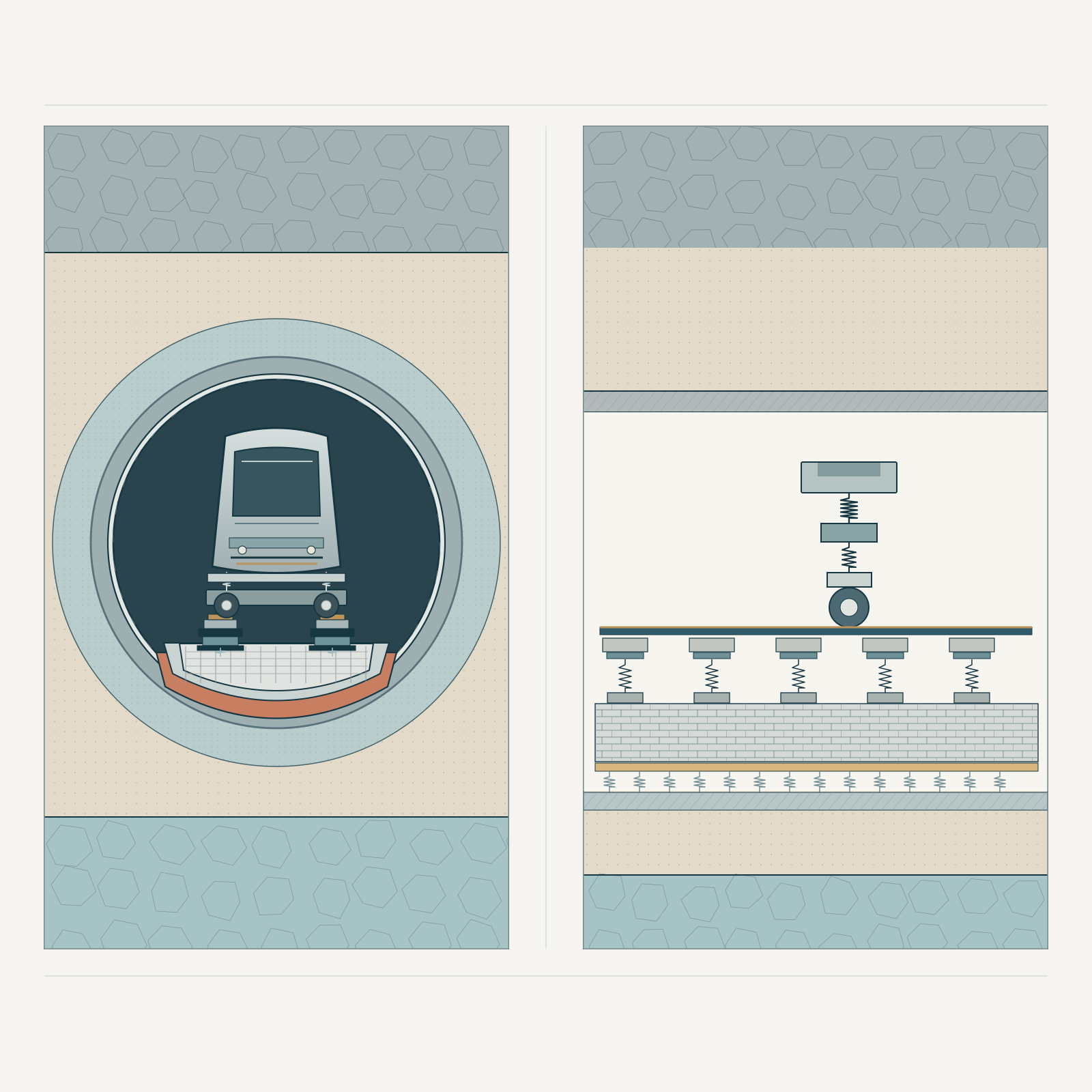
Efficient physics-based prediction of coupled vehicle–track–structure–ground response for systems with regular or continuous geometries.
- Wave-number domain and 2.5D semi-analytical formulations
- Vehicle–track interaction, Hertzian contact and roughness excitation
- Track receptance, rail/fastener/slab dynamics and periodic coupling
- Rapid parameter studies, system sensitivity and mitigation optimization
Finite-element analysis
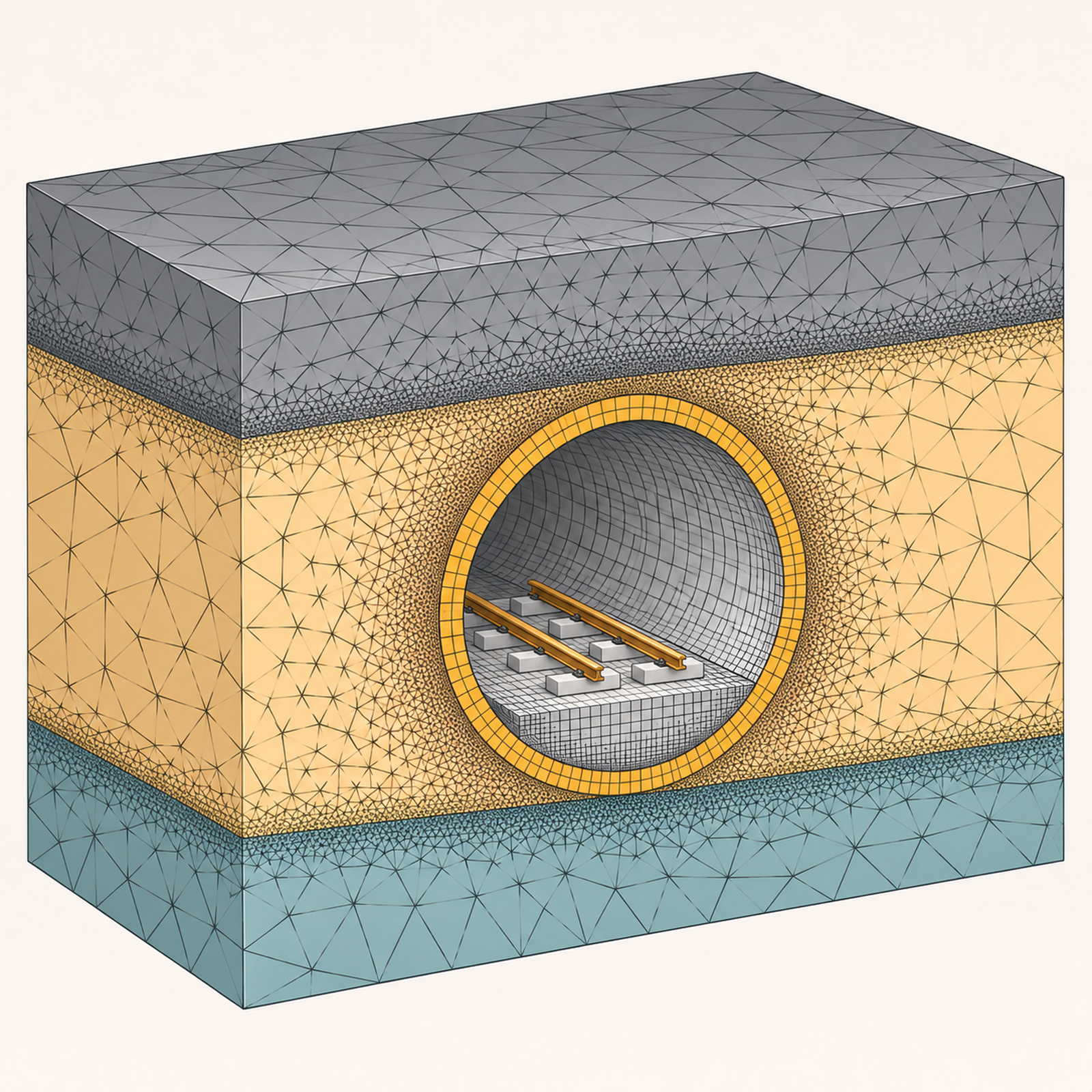
Detailed numerical treatment of complex geometries and structural configurations when simplified idealizations are insufficient.
- Tunnel, at-grade and viaduct configurations with detailed geometry
- Structural dynamics and three-dimensional soil–structure interaction
- Complex material, foundation and boundary conditions
- Local responses, dynamic transfer functions and building coupling
Vibration prediction & diagnostics
The coupled system models yield receiver-level vibration and re-radiated ground-borne noise estimates, along with component-level information needed to understand transmission mechanisms. Results can be examined in the frequency domain and in conventional octave or third-octave bands.
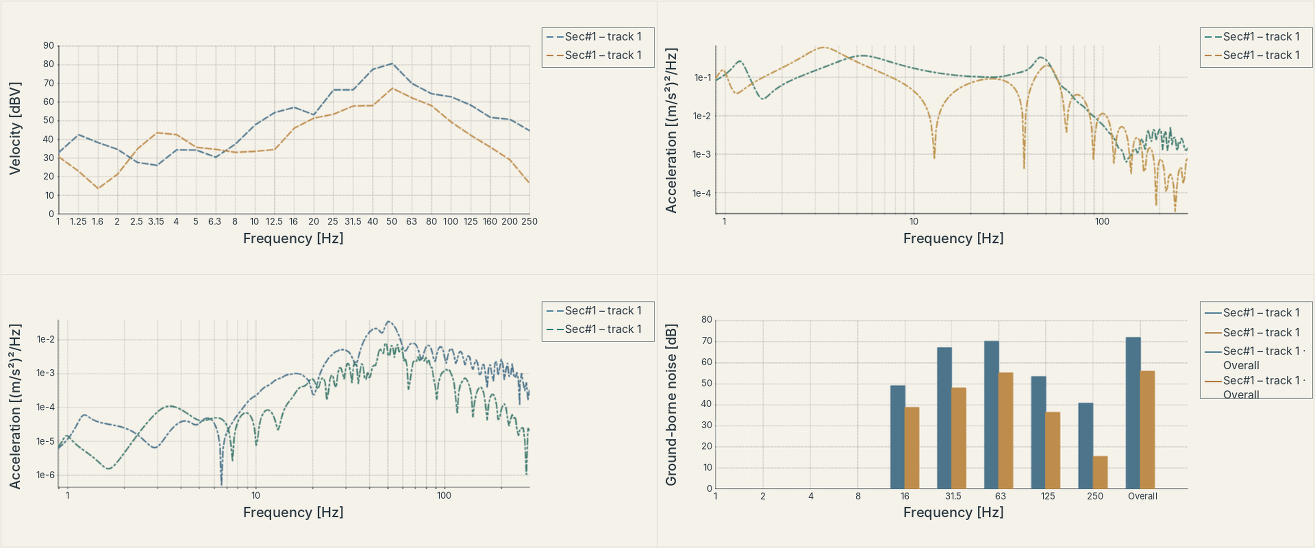
Physical response
- Displacement, velocity and acceleration responses are predicted throughout the coupled railway–ground–building system.
- Depending on the assessment objectives, results are evaluated using RMS values, amplitude spectral density (ASD) and power spectral density (PSD).
Frequency-domain results
- Vibration response spectra and ground-borne noise levels are evaluated and presented in octave and one-third-octave frequency bands.
- Dominant frequency ranges are identified, and predicted responses are assessed against applicable criteria.
Transfer characteristics
- Driving-point and transfer frequency response functions (FRFs), modal characteristics, resonances and anti-resonances are analysed to identify vibration transmission, amplification and attenuation mechanisms within the coupled system.
System diagnostics
- The sensitivity of predicted responses to key model parameters is evaluated, together with the contributions of individual transmission paths.
- Dominant mechanisms governing vibration propagation and receiver response are identified to support engineering assessment and mitigation design.
Corridor-wide vibration mapping
Ground-borne vibration can be evaluated spatially along a railway alignment, rather than only at isolated receiver points. Railway-aligned mapping provides a corridor-level view of predicted vibration response, nearby sensitive buildings and sections requiring more detailed assessment or mitigation.
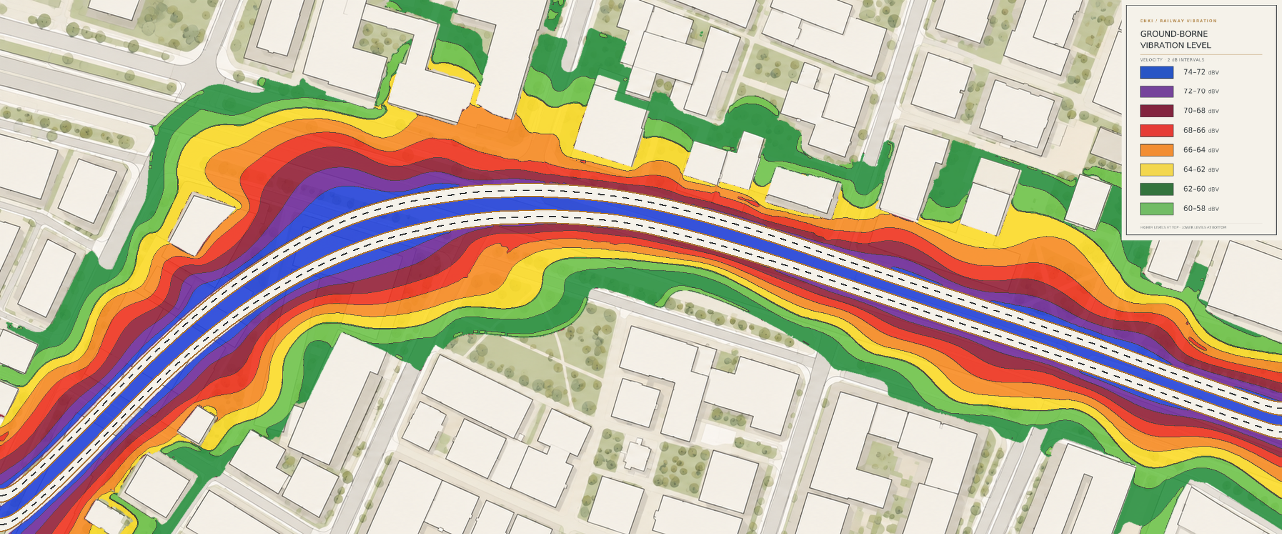
Spatial prediction
Distribution of ground-borne vibration along and across the alignment, based on route geometry, infrastructure and the applicable propagation model.
GIS-based interpretation
Integration of track geometry, ground conditions, receiver locations and predicted response into railway-corridor visualizations.
Engineering decisions
Identification of elevated-response sections, sensitive receivers and priorities for subsequent detailed assessment and mitigation design.
Trackform mitigation & vibration isolation
Mitigation strategies are developed and evaluated within the same predictive system used for baseline assessment. Resilient fasteners, floating-slab mass–spring systems and other trackform modifications are compared on the basis of dynamic behaviour and resulting receiver response.
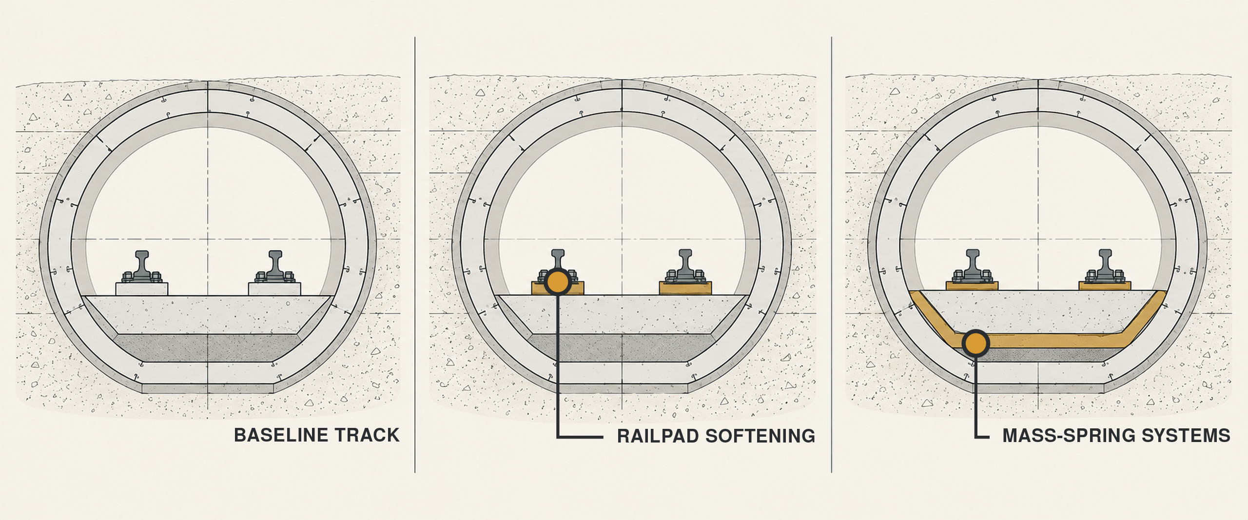
Practical Track Form Design
- Comparison of alternatives with respect to performance, integration and project-specific engineering constraints.
Railpad Softening
- Introduction of resilient fasteners and rail pads in order to manipulate the resonance frequency of rail-sleeper coupling and provide more attenuated vibration velocity in post-frequency ranges.
Mass–Spring Systems
- Introduction of continuous or discrete resilient support padding under the track slab in order to further reduce vibration velocity at receiver responses.
- Assessment of slab mass, resilient support properties, eigenfrequencies and transmitted vibration.
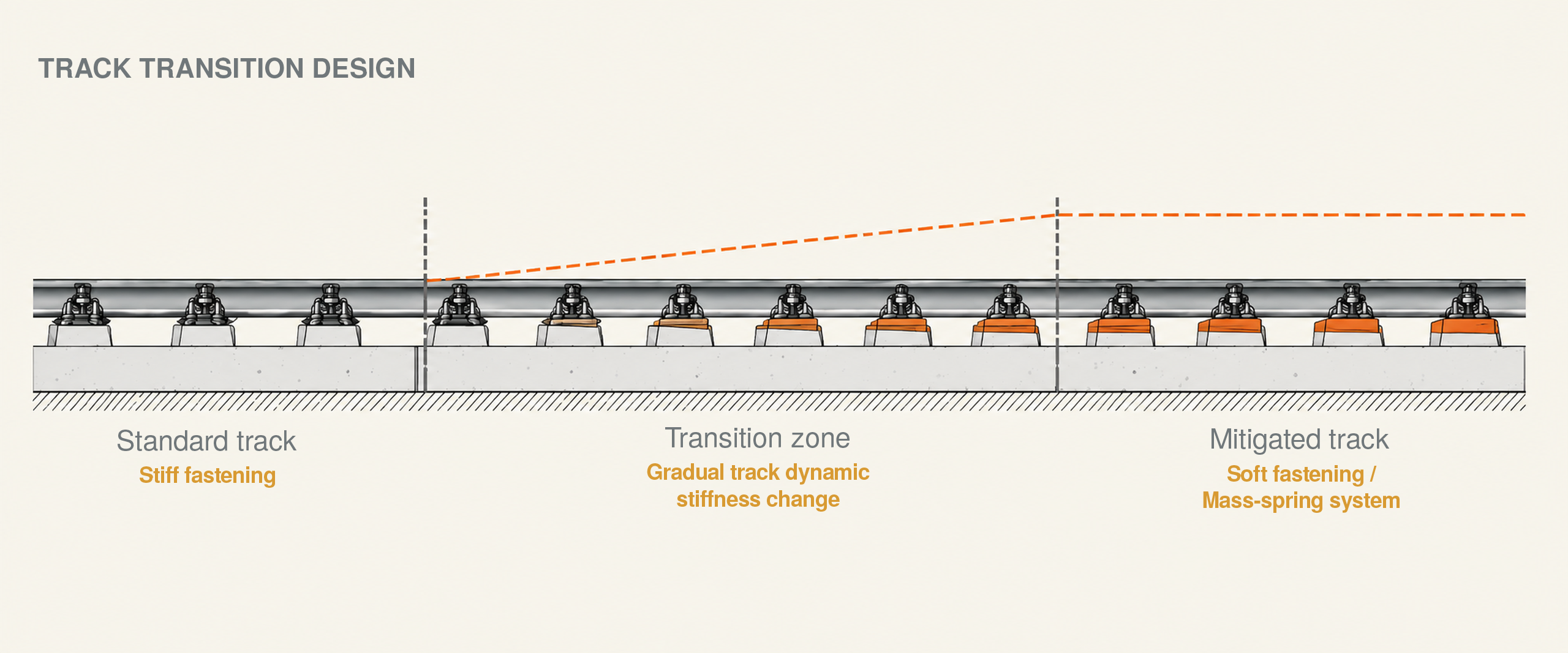
Transition-zone design
- Gradual adjustment of track dynamic stiffness between conventional and vibration-isolated track sections.
- Optimization of rail pad and resilient support properties to control wheel–rail interaction forces and minimize dynamic amplification.
- Assessment of transition-zone performance through coupled dynamic modelling, considering resonance behaviour and vibration transmission.
Insertion Loss & Uncertainty Analyses
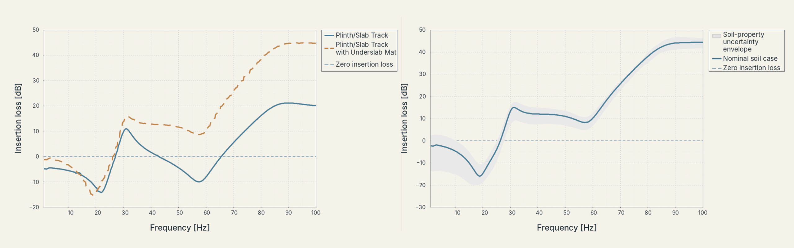
Trackform alternatives are assessed through their frequency-dependent response and predicted insertion loss. Comparative calculations reveal where a measure reduces transmission, where resonances may limit its benefit and how design parameters can be optimized for relevant receivers.
The effects of defined ranges in key model parameters, including soil stiffness and resilient support properties, on predicted insertion-loss performance are evaluated. Response envelopes are used to identify sensitivity and assess the robustness of mitigation measures.
DIAGNOSE
Identify governing physical mechanisms
OPTIMIZE
Evaluate resilient support and track parameters
SIMULATE
Calculate response and insertion loss
ASSESS
Assess receiver performance against criteria
Criteria, compliance & design verification
Predicted ground-borne vibration and noise levels are evaluated against project-specific requirements and applicable guidance. Criterion selection considers building use, receiver sensitivity, the relevant frequency range and assessment metrics. Comparative performance and compliance margins support final mitigation design decisions.
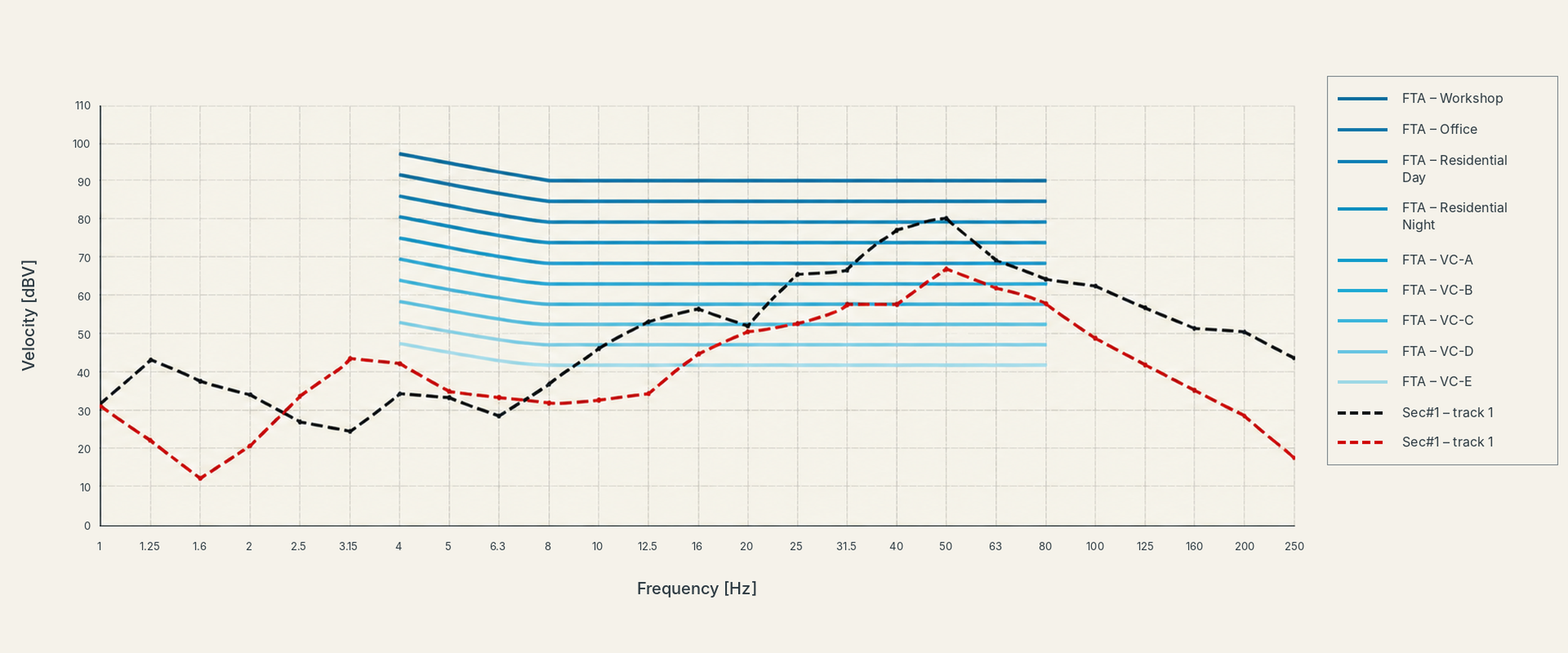
International standards & guidance
The following references inform assessment where applicable; their use is determined by the specific project and jurisdiction.
Transit Noise and Vibration Impact Assessment guidance
Ground-borne vibration and noise arising from rail systems
Evaluation of human exposure to vibration in buildings
Effects of vibration on people in buildings
Effects of vibration on structures and buildings
Applicable national codes and project-specific requirements
From prediction to engineered mitigation.
Explore selected railway projects involving vibration assessment, modelling and mitigation design.